Common 3D Model Errors
You have spent countless hours designing your parts and you are finally ready to print, but it would be a shame to fall at the final hurdle, wouldn’t it?
Design is crucial and having the knowledge and the ability to understand and fix errors will ensure that you can print quality parts.
This guide is your simple checklist that you can refer to, to ensure that you are sending us a fully optimized file for 3D Printing!
Triangles, Edges & Contours
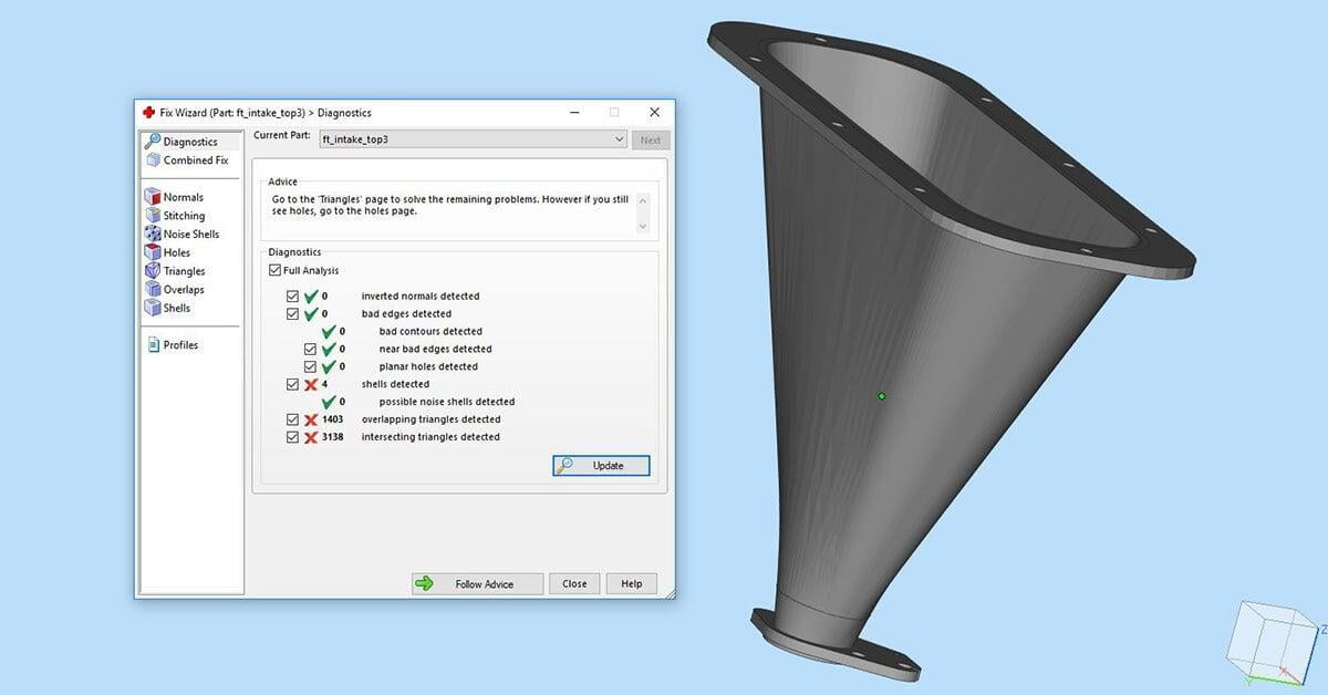
Overlapping Triangles
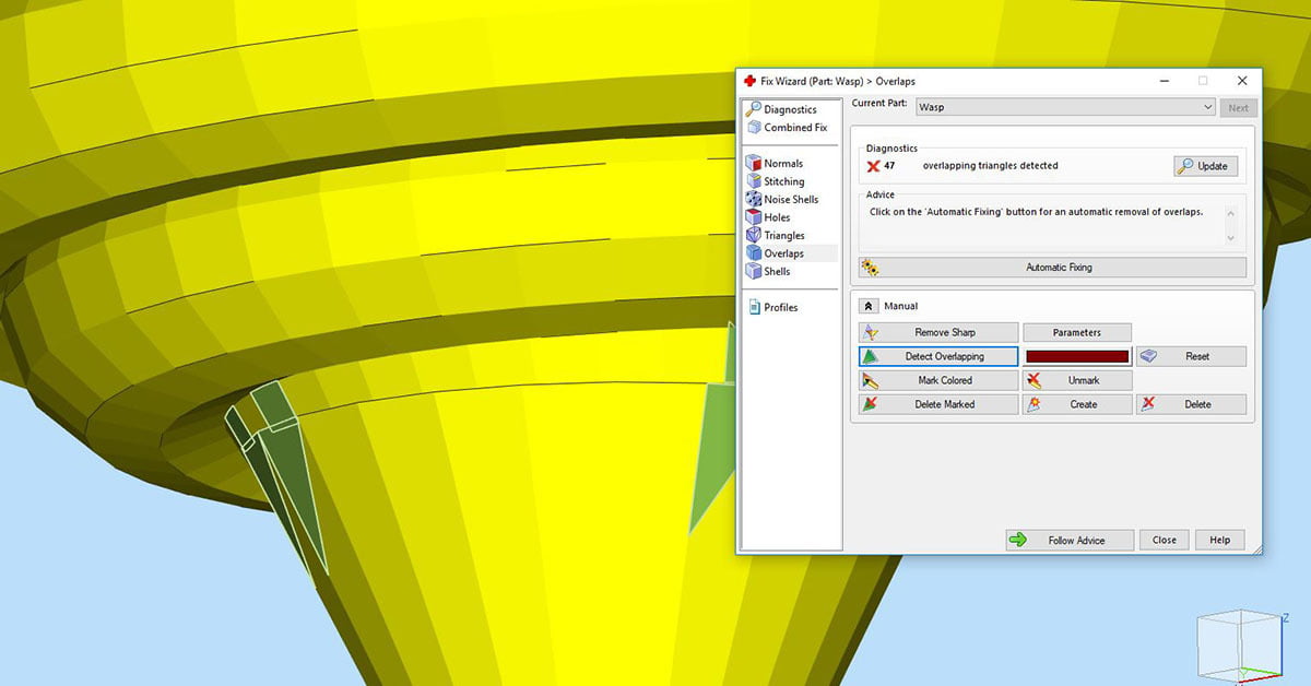
These occur when your files contain double surfaces, that aren’t connected to any other surface. These overlaps can cause issues if not removed prior to printing.
Intersecting Triangles
These occur when your files contain double surfaces, that aren’t connected to any other surface. These overlaps can cause issues if not removed prior to printing.
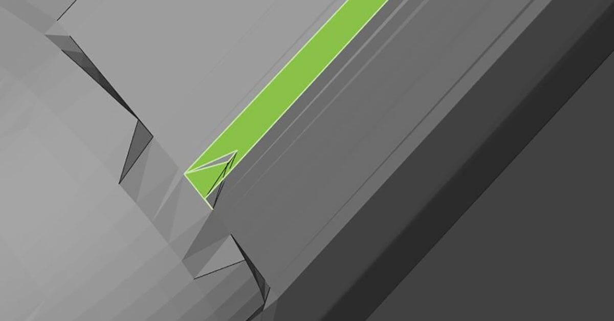
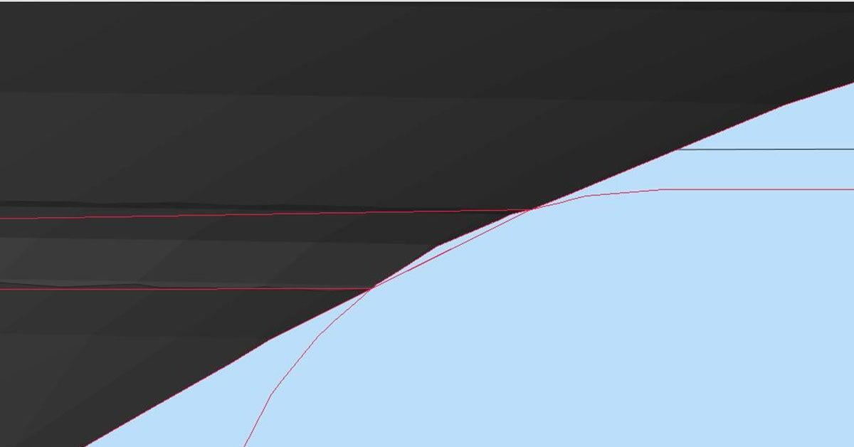
Bad Edges & Contours
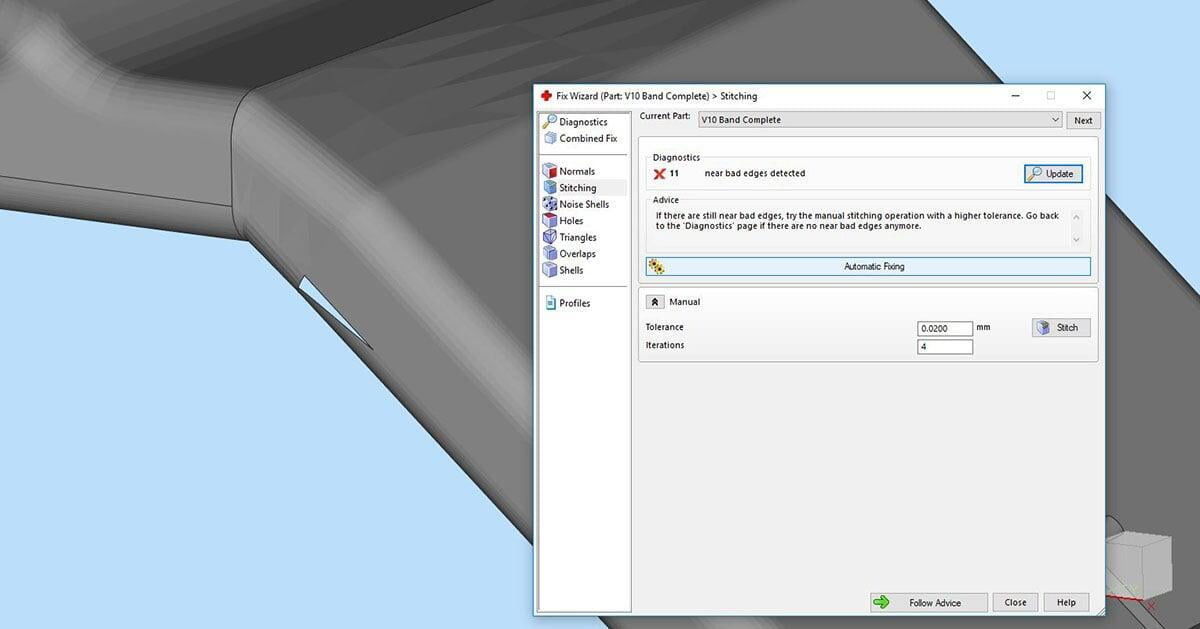
Those annoying triangles are causing issues, again aren’t they? Bad edges result from triangles not being full connected to each other. It may be difficult to see physically but if it is not resolved it will result in gaps between surfaces. Many bad edges together are known as bad contours.
Shells, Normals & Wall Thickness
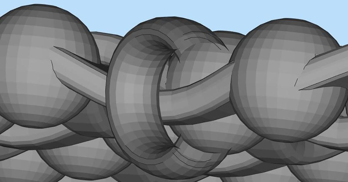
Shells
Refers to the outside perimeter of each layer on your object. Shell thickness is customizable depending on what you require. Without shells, objects would be printed as a complete solid rather than hollowed out. Imagine a cup, if you didn’t have any shells then it would printed as a solid.
Noise Shells
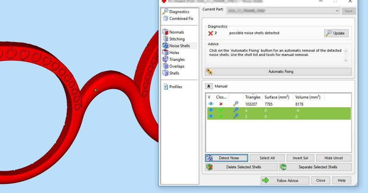
Are so small in volume they can appear as bumps and uneven surfaces in your Parts.
Inverted Normals
Normals determine whether the surface is an inner or outer surface. Normals are vital as they tell the printer which side of the face is being printed. Inverted normals occur when a normal is actually pointing in the wrong direction.
Wall Thickness
Wall thickness is crucial to a prints success. It refers to the distance between one surface and its opposite inner surface. Wall thickness has a minimum requirement which is 0.5mm, with a tolerance of 0.2mm on the X & Y-axis and 0.3mm on the Z-axis.
Important Considerations
STL File Resolution
STL files are comprised of many connected triangles which make up the surface of the part. The higher the resolution, the higher the number of triangles, which in turn increases the overall size of the file; in fact this is much similar to the resolution of a video.
A lower resolution will result in a smaller file, but triangles will actually become visible to the naked eye when printed. Therefore, it is important that your resolution is not low. We would recommend choosing a resolution on the higher side. It is also worth considering the reason for printing. If it is a prototype, a lower resolution may suit but if it is the final part then a higher resolution would be needed for an optimal surface finish.
Download MJF Recommended Formats & Resolutions
Information Pack

Exporting the STL File
When exporting your 3D File from your CAD software we recommend that you save it in STL format. Why? STL file format is recognized by all 3D Printing machines. Essentially it acts as a language, which the printer can read and use this information to print the parts. Not all file formats work on every printer, therefore STL is the most universal option.
Introduction to Design Optimization
Files Hollowing